In order to use the Ncompass™ Analyzer, it is necessary for the User to design, build and test interface adapters (IA) which enable the Analyzer to be electrically connected to the Unit Under Test (UUT).
Given the many different permutations of electrical and electronic circuitry likely to be tested, and the multitude of electronic interfaces (plugs, cables, connectors) that are likely to be encountered, it is impossible to pre-fabricate a one-size fits all IA that will couple the Ncompass™ Analyzer to all possible types of UUT. Therefore, for each different UUT a bespoke interface needs to be made.
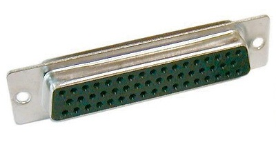
The standard interface connector on the Ncompass™ Analyzer (portable and rack-mounted versions) is a 50-Pin D-sub female connector, illustrated below.

Refer to the Ncompass™/NODES™ User Manual for more information on the design, build and testing of specific IA, and the cable types that can be used.
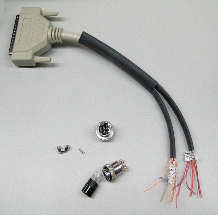
With the IA design completed and the pin-outs identified for the IA, the construction of the IA can commence. This requires the correct identification of each wire in the 50-pin D-sub cable in order to correctly attribute each wire to each connector pin and to each Test Point. To ensure the correct wire is identified, an electrical continuity test between the UUT termination and each pin on the male D-Sub connector at the other end of the interface cable should be carried out.
The small size of the D-sub connector means that adjacent pins are located extremely close to one another and this means that identification of specific pin and/or carrying out a continuity test can be a fiddly and time-consuming task. Problems that regularly occur are:
Ø The wrong pin is selected for connection.
Ø Two or more pins are inadvertently breeched during connection.
Ø Technician miss counts and tests the wrong pin.
Ø Multiple “re-checks” are required to confirm correct connection.
Ø Bending of or damage to pins during access.
Ø Poor connectivity, leading to false open circuit indications.
Ø Difficulty in testing for shorts between other pins.
Using the BoB MKII overcomes all of these problems and so this provides the User with an efficient and effective wiring identification tool when pinning-out and constructing the IA.