The BoB MKII is enclosed in a fully protective and portable carrying case. Its integral construction means that it does not need to be removed from the box for connection or operation and it can be used in working environments from the laboratory to in the field.
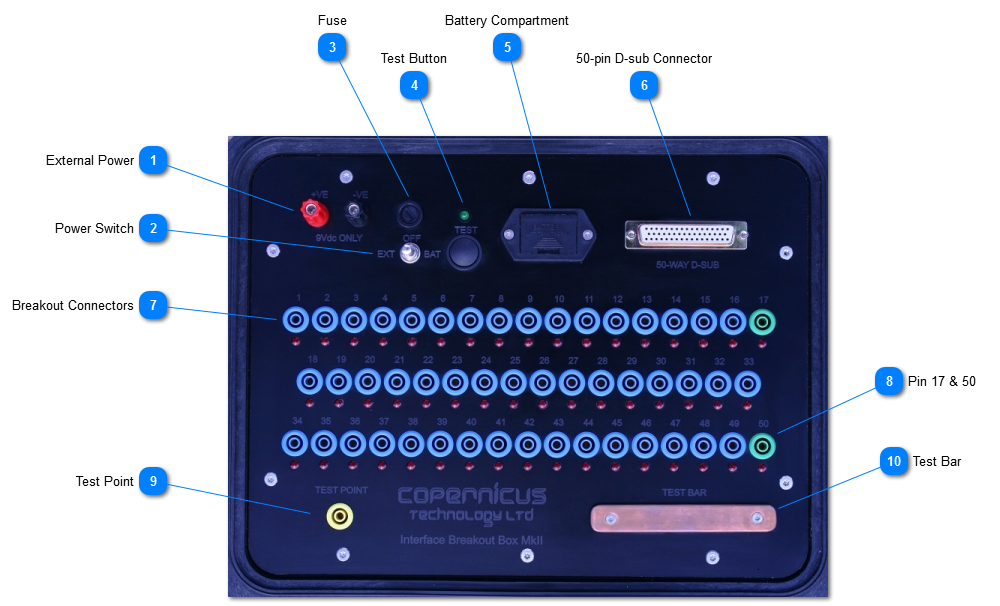
External Power
4mm post connectors for connecting external power - maximum of 9VDC.
Three position gated switch to allow selection of the power source from External to Internal. The switch should be placed in the OFF position when not in use. See Power Modes on how to connect an External power source.
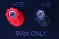
Press to Test is used to ensure that the power source selected is compatible to the correct functioning of the BoB MKII. If the test is satisfactory, then the green LED will light and the buzzer will sound.
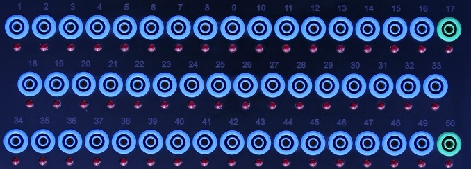
The Ncompass™ Analyzer uses these 2 pins differently to the other pins on the 50-pin D-sub connector, and so these are coloured green to provide a visual reminder to the user. For more information on the use of these particular pins then consult the Ncompass™/NODES™ User Manual.
Using the Test Point the User can probe the other end of the IA; this will in turn illuminate the corresponding LED for the pin on the 50-pin D-sub connector that has been connected.
Using the Test Bar the User can brush the other end of the IA’s exposed cables on to the bar; this will in turn illuminate the corresponding LED for the pin/s on the 50-pin D-sub connector that have been connected. Note that the more cables within the 50-pin D-sub connector that are made, the dimmer the LEDs will be.